Complex IOR


  • Where to find it: (These Nodes are available in the Nodegraph only)


    • NodeGraph / Right Mouse Click / Add Nodes / Workflow Conversion /


Dielectric materials (non-metal) can have their Fresnel effect rendered based on their refractive index alone. 

For metals, however, their reflectance curve also depends on other variables, and in order to achieve a precise Fresnel effect for a given metal (e.g. gold, copper, etc.), 

you can use Complex IOR conisting of the variables N (Refractive Index) and K (Extinction Coefficient).

As these values are no very user friendly, many Render Engines offer Abstractions of them in form of a Reflectivity Color (also called Specular Color) as well as Edge Tint Color.

The Complex IOR Node allows conversion between the two methods in both directions e.g. 


  • N,K to Reflectivity,Edge Tint
  • Edge Tint,Reflectivity to N,K


You can then output texture maps to map the effects.


Tutorials: Converting N,K Values to Reflectivity,Edge Tint and vice versa

As the method to obtaining and converting N and K values has its pitfalls, below is a short tutorial how to correctly get, set and convert N & K Values to Reflectivity Edge Tint as well as the other way around


To obtain our N and K Values we will use the page https://refractiveindex.info/


  1. Pick a material of your choice. Here we choose Gold (Au)


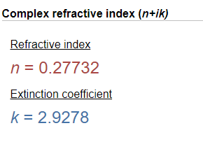
  2. You can see the N and K Values for the given Wavelength being displayed

  3. Next we need to get the individiual n,k values for the colors red,green and blue, so we can use it in our node.
    To do that we need to enter three different wavelengths in the wavelength field above the Complex refractive index.

    The wavelength field


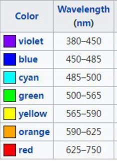
  4. Let's first find the wavelengths for red, green and blue light. We can use google to do so 


  5. You can see the values we obtained from google are in nm however we need them in µm.
    We can use the Unit Converter Button to convert them


    However in general all you need to do is divide the nm unit by 1000.

    For example for Red, we take the maximum wavelength 750 nm and divide it by 1000, giving us a value of 0.75 µm

  6. Let's get the correct N,K values for red, green and blue. 
    We are using the maximum wavelength here, however you can choose a value between its minimum and maximum as required


  7. Next let's go into our Complex IOR Node in Mari.
    By default the N and K values are represented by a single slider, however we need three separate values.

    To expose the individual values, we click on the "S" Button next to the slider

    Clicking on the S Buttons will decompose the Slider into individual Values


  8. Let's enter our previously determined N and K Values into the Fields. We leave the last entry at 0.0.


  9. The converted Reflectivity and Edge Tint will now be output on the respective ports of the Node


  10. If we view one of the ports, when it is not connected to a scalar input (e.g. a scalar Channel), Mari will by default display it color managed in the viewport

    For pure viewing purposes we can temporarily deactivate the Color Management by clicking on the Color/Scalar Toggle in the Color Management Toolbar:
    You do not need to do this. It is just illustrated here in order to see correct values directly in the viewport.  Remember to turn it back on after viewing.

    We click on the "Color" Wheel in the Color Management Toolbar, so it is greyed out, 
    indicating that Color Management is currently disabled


  11. If we now attach a Viewer Node (Hotkey 1) to the Reflectivity or Edge Tint Output Ports, we see the "artistic" representation of the physical N and K Values


  12. You can now use this node output(s) and feed it into a scalar channel, that you can use in your rendering engine


Converting existing Reflectivity and Edge Tint colors back to N & K values is relatively straight forward, with mostly Mari UI elements to watch for.


  1. Using the Color Fields in the Node and the Mari Color Picker,  add your Reflectivity and Edge Tint Colors


  2. When entering values, make sure that the Color/Scalar Toggle is set to Scalar.
    The Field next to the respective color field should appear grey - if it doesn't, click on it once.


  3. Fully expand the Color Picker, so you see all additional options (you can resize the dialog if you do not see the info below)

    Inside the color picker, the Color Space Option should be greyed out and the Color/Scalar Field next to it appear grey as well.

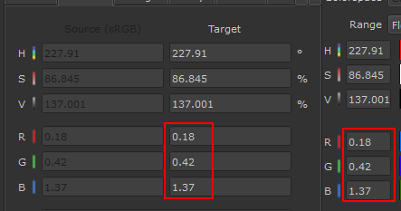
  4. Use the R,G,B Value Fields to enter your color values


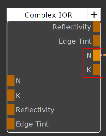
  5. The N and K Output Ports of the Node will give the converted N and K Values


  6. If you want to see the values those ports return, view the output of the node, then again open a color picker, for example by clicking on the Background/Foreground Colors in the Tools Toolbar


  7. Again fully expand the Color Picker

  8. If not already the case, click on the Color/Scalar Toggle, so it is greyed out

  9. Set the Canvas Color Pick Mode to "Pick Raw Pixels"

  10. Using the Dialogs Color Picker value, pick the value in the viewport.


  11. You can see the picked values either in the RGB Fields or in the "Values" Tab


Node Overview

Node Ports


  • Reflectivity

Outputs the Reflectivity Color of  the conversion from N + K values


  • Edge Tint

Outputs the Edge Tint Color of  the conversion from N + K values


  • N

Outputs N (refractive Index) of the conversion from Reflectivity + Edge Tint colors


  • K

Outputs K (Extinction coefficient) of the conversion from Reflectivity + Edge Tint colors


  • N

Feeds in the N Values (refractive index) into the Node. If the port is mapped, the "N" Values inside the Node are ignored.
Commonly N consists of 3 unique RGB Values. The Alpha is ignored.
N is used to convert to Reflectivity and Edge Tint.


  • K

Feeds in the K Values (Extinction coefficient) into the Node. If the port is mapped, the "K" Values inside the Node are ignored.
Commonly K consists of 3 unique RGB Values. The Alpha is ignored.

K is used to convert to Reflectivity and Edge Tint.


  • Reflectivity

Feeds in Reflectivity Color into the Node. If the port is mapped, the "Reflectivity" Color field inside the Node is ignored.
Reflectivity is used to convert to N and K.


  • Edge Tint

Feeds in Edge Tint Color into the Node. If the port is mapped, the "Edge Tint" Color field inside the Node is ignored.
Edge Tint is used to convert to N and K.


Node Properties


To decompose the single slider value into 4 unique values, click the "S" Button


  • N

Feeds in the N Values (refractive index) into the Node. If the N port is mapped, the "N" Values of this field are ignored.
Commonly N consists of 3 unique RGB Values. The Alpha is ignored.
N is used to convert to Reflectivity and Edge Tint.
Enter three separate values by clicking on the "S" Button


  • K

Feeds in the  K Values (Extinction coefficient) into the Node. If the K port is mapped, the "K" Values of this field are ignored.
CommonlyKN consists of 3 unique RGB Values. The Alpha is ignored.
K is used to convert to Reflectivity and Edge Tint.
Enter three separate values by clicking on the "S" Button


Despite being colors, the values should be treated as Scalar.
Make sure the Color/Scalar toggle is set to "Scalar" (it should appear grey)


  • Reflectivity

Feeds in Reflectivity Color into the Node. If the corresponding port is mapped, the "Reflectivity" Color field inside the Node is ignored.
Reflectivity is used to convert to N and K.


  • Edge Tint

Feeds in Edge Tint Color into the Node. If the corresponding port is mapped, the "Edge Tint" Color field inside the Node is ignored.
Edge Tint is used to convert to N and K.


Determines the Algorithm used for conversion

Belcour is generally considered the more modern algorithm with better Energy Conservation.

  • Gulrbandsen

Gulbrandsen's Algorithm is fast and efficient. It modifies the traditional Schlick Fresnel approximation, to produce more accurate results, especially for dielectrics (non-metals)


  • Belcour

Belcour's Algorithm focuses on physical accuracy over pure efficiency. It is an algorithm more often found in Offline Renderers compared to Gulbrandsen, which is more suitable for realtime.
Belcour tries to simulate multi-layer Fresnel Effects, accounting for light interactions between layers.


Please note, the Node doesn't use the full Belcour Algorithm but a version more suitable for realtime preview. While still more expensive than Gulbrandsen it is considerably more lightweight than the full Belcour implementation